• Hello Guest, welcome to the initial stages of our new platform!
    You can find some additional information about where we are in the process of migrating the board and setting up our new software here

    Thank you for being a part of our community!

240 "Brake Failure" light

How can I tell if I have ATE or Girling calipers? Do they mount differently? If they have the same mount, does it matter if I have ATE on one side and Girling on the other?
 
How can I tell if I have ATE or Girling calipers? Do they mount differently? If they have the same mount, does it matter if I have ATE on one side and Girling on the other?

bromsok.jpg


http://forums.turbobricks.com/showthread.php?t=326963
 
Replacing the caliper was easy, but that brake still wouldn't bleed. Had to take it to a shop. They say the correct procedure is a "gravity bleed" where all of the bleed valves are open all night. Does anybody here have experience with that? Does anybody here know why the "proper" procedure (see my 6-19-2017 post) isn't correct?

Turned off the brake failure light by unplugging the wire from the brake proportioning valve, removing the post the wire attaches to, applying light pressure to the brake pedal, reinstalling the post, relieving pressure from the brake pedal, reinstalling the wire.
 
Hello people of Turbo Bricks,

Firstly, sorry to dredge up and old post :repost:. Thank you for the above information and photos, they have been quite helpful. I am currently working through eliminating the brake failure light fault and have traced it back to the brake like j-box. There are no leaks but pulling it apart and testing it for functionality with a ohm meter, I get a closed circuit resulting in the light illuminating.

Anyway, my question is, can i just reuse the j-box without the switch connected up to it? Should i remove the internal compontents as I assume the replacement j-box for the later models does not have the switch installed as a part of it? This way I can order the level sensing brake fluid reservior (hoping I can find one) and use the brake light circuit for this part instead of the j-box.

A side note - I'm an electrician by trade (not automotive) and the photo in the post says 'thin insulating band prevents contact from closing circuit when centered'. From my testing the thin insulating band doesn't actually seem to "insulate", electrically speaking anyway (as it also gives a short circuit), it more just appears to be a physical switch which moves when the brake pressure is out? I'm not quite sure of the functionality of this j-box switch as as soon as the pin touches the insulating band I get a closed circuit resulting in the brake light illuminating. I would think that either the band has broken down or something else? Perhaps my j-box is fine, just something I'm not understanding about it's functionality.

Thanks for your time in advance.


Tl;dr - Can I reuse my existing brake line j-box (no leaks) and if so do i need to remove the internal components as per the picture above.
 
FYI, a faulty brake master can cause the light to come on too. And a brake master can loose a circuit and not leak.

The described function of the switch by cleanflametrap is correct. That band is supposed to be non conducting. The brake failure light on the dash has switched power and ground is supplied to make the light come on when the "shuttle" inside the junction/manifold moves due to an imbalance or a leak.

You shouldn't remove the guts as this would create a complete loss of brakes.

How did you determine the "short circuit"?

And if by chance you want 1, I sell a new later version brake junction/manifold that doesn't have the built in warning switch and will never leak and a new brake reservoir cap with a float switch to replace .

http://forums.turbobricks.com/showthread.php?t=345823
 
Last edited:
Hi Eric,

Thanks for your reply. I have already replaced the brake master cylinder for new although I'm not sure this was a part of the problem.

In regards to the "short circuit", what I mean is when I put my meter between the band (in the centre position) and ground I get 0.1 ohms. When I screw in the plastic plug (with the spade connector on it) into the jbox the brake light illuminates when it's screwed about 3/4 if the way in, therefore completing the circuit to ground. The band is definitely in the center position when doing this. If this band was insulated I would think it would be an open circuit?

Out of curiosity, if the band moves to the side and the pin pushes through, what does the pin touch to actually complete the circuit to illuminate the break light? Assuming everything was working correctly.

I think I'll have to look at getting a reservoir cap but I'm wondering if I can still use the jbox as it isn't leaking. This way I can put it all back together and still use the vehicle before waiting to get another box. :D

BTW, I'm in Australia so I'm mindful of shipping costs and our horrible exchange rate. I also like getting authentic parts if available so I might have a little hunt around before ordering a part of yourself and see if there is anything local. I'm hoping I can just reuse the jbox and order a cap with a float local but I'll definitely be in contact if I can't find anything. Even so do you think you could let me know a break down of costs and shipping to Australia, area code 4700.

Thanks again for putting your time aside to help out. Greatly appreciated.
 
Interesting, getting such a low resistance reading from the band. It's plastic.

I've not taken the shuttle tube apart to find out how thick that plastic is, or fully understand how it is assembled (shrunk?) to the center part of the tube that is cut for it. Maybe it is thin enough for the pressure of the spring-loaded switch pin to eventually pierce through after years of pressure in the same place. You saw that one picture of mine showing the dent in the plastic.

My experience with false warning light from that switch is the conductivity of the brake fluid heavily contaminated with moisture and iron oxide is sufficient to turn the light on visibly. The leakage is tiny, so washing out the switch cavity puts the light out for years. I assume flushing with fresh fluid might help too with the longevity of the fix.

And finally, though this doesn't explain the light, I would mention that over the years I've come to realize a good number of multimeter resistance readings have been taken with damaged instruments. It is very easy to mistakenly check a live circuit in "ohm" setting and instantly turn a low-ohm range into one that works like R-times-one-meg without realizing it happened. Any reading that doesn't seem right should be followed up by a check of a known resistance in that same range.

So, is your brake failure light on with the engine running, but no foot on the brake pedal, or does it come on when you step on the brake? That would be the difference between a hydraulic failure and an electrical fault.
 
Hello creetus,

When the shuttle moves far enough in 1 direction, the pin will make contact with 1 of the conductive sections on the ends of the shuttle both of which are in contact with the inside of the junction/manifold which is grounded to the frame via the mounting screw.

I was at a loss to explain your problems with the warning light as I haven't experienced those exact symptoms. I was thinking about rust in the system and it appears Art has already dealt with that issue. So you might be able to get it working again by cleaning the switch passage. I suggest using some spray can brake clean followed by some compressed air. If that doesn't work you might have to take it apart to do a more thorough cleaning to get it work properly.

Something for everyone to remember, the seal for the warning light switch is just a dust seal and there should never be any brake fluid in the warning switch passage. The o-rings on the end of each "piston" inside the junction/manifold are supposed to keep brake fluid from getting past.

If needed, shipping for the kit to Australia will be $25.00 USD.
 
Last edited:
Thank you cleanflametrap for the detailed pictures!

I've noticed whitish corrosion on the bleeder valves along with some rust in the fluid. Is it possible to unscrew the switch from the junction box with it still mounted to the car without disconnecting all of the other lines? I'd like to clean it up a bit before I bleed the system, but don't want to touch it if it involves disaster.[


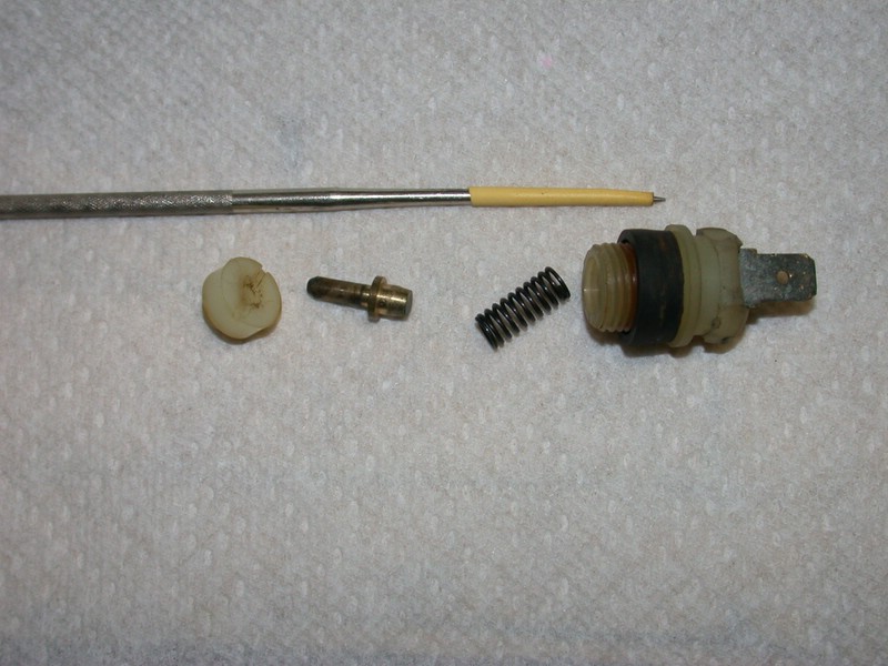
QUOTE=cleanflametrap;4282143]I've found this switch is capable of giving false alarm. That is, you can get a light even though it hasn't sensed an imbalance between the two brake circuits; the shuttle is still centered.

Assuming you are getting the light without having to step on the brakes, here's how you might find out if the shuttle is stuck to one side, or a small fluid leak in the switch is the cause of the warning light.

1. Disconnect the D+ from the alternator (small red wire). This allows you to disable lamp test mode without having to run the motor.

2. With key in KP-II, have someone observe the failure light while you disconnect the spade from the octopus and provide a solid, clean ground to the wire. If an assistant is impossible, an ohmmeter will get you to the same place without the need to test the lamp brightness.

3. If the light is just as bright connected to the octopus as it is directly grounded, the shuttle will be found to be stuck to one side. This would tell me I need a new one, and the conversion to 91 is my choice -- just be aware the correct float reservoir was only used on 91 non-ABS cars, as was the 8-port plain manifold.

4. If the light is brighter directly grounded, then you may be able to fix this by merely removing the switch and cleaning the rusty brake fluid from the cavity.

Note. When you remove the nylon switch body, the rust swollen first few threads in the block may make it a royal pita to re-install it. Chasing the threads with the flutes of an appropriately pitched tap will help.

Don't forget to reconnect the D+ wire as soon as you're done testing.


octopus5.jpg


[/QUOTE]
 
Is it possible to unscrew the switch from the junction box with it still mounted to the car without disconnecting all of the other lines? I'd like to clean it up a bit before I bleed the system, but don't want to touch it if it involves disaster.

Certainly you can unscrew the switch using a deep well six point socket without disaster.

If the car lived up in the rust belt, you might have some fun starting the threads to re-install the switch, as I've had, but with some careful cleaning of the first few threads on the switch cavity, you'll get it back in.

If there's any brake fluid behind that switch, it will only be a few drops; a half-teaspoonful at most, unless the octopus is leaking past the o-rings enough for it to show up outside the switch. In that case you'd need to replace or rebuild the unit anyway.


Hi cleanflametrap, there was about a half-teaspoon of brake fluid when I unscrewed the sensor which was very corroded. I was able to get all of the fittings loose on the octopus, and have placed an order for two o-rings. I disassembled the two ends and found that there was a bit of corrosion on the sliding contact barrel and inside the chamber where the two 21mm hex head stoppers are along with rusty buildup. The thick tar coating really prevented much damage though to outer body and threads for the most part.
 
Ah, you are patient and ambitious. I hope you will post the story of your octopus rebuild. :)


Hi cleanflametrap, this was my plan. I had everything cleaned and ready for the two o-rings which I had ordered. A few days later, the company said they no longer had them in stock. Then, at around the same time, I had a note on my windshield saying I had to move the car or else it would be towed. Luckily, planetman saved the day. He had one to me in just enough time to have it installed, bled, and off of the jack-stands.


Only one of the o-rings looked rough. It might explain why the front part of the master cylinder's fluid level was lower than the back.
 
Sorry to once again revive a dead thread...

Is there a rebuild kit for the switch? If there is would someone kindly recommend a source?

Closest Volvo parts dealer is 80 miles away..
 
Just thought this might help someone else.

I verified I had braking power at all wheels to assume my issue was the switch.

Got the switch to start working again and the light off.

Used a 14mm deep 6pt socket and pulled the plastic threaded switch housing, yanked the spring and had to use pliers to pull the switch pin out of the octopus. As the pin was all gunked up. Used brake cleaner and hosed out the octopus and polished up the pin. Used a drop of pb blaster in the octopus switch cavity and a little dielectric grease on the o-ring and all is good now.
 
Back
Top